Marine Exhaust systems have confounded Marine Engineers, Marine Engine Service Companies and Boat Builders since they first installed an engine in a boat Although Power Driven yachts and commercial vessels continue to have challenges, it is the modern sailing yacht that seems to suffer the most. So, we will limit the conversation to Diesel Exhaust Systems in Sailing Yachts. Being as the subject is so complex that it confuses some of the best minds in the marine industry, it is impossible to comprehensively cover the subject in one article. But we will give it a try.
Every time we get a call about a marine engine that won’t crank, the first thought we have is that there may water in the cylinder which has created a “hydro lock”. All too often, we are correct. If the situation is caught in the very early stages, the engine can be salvaged by removing the injectors, cranking the water out of the cylinders, and then running the engine under load at 50% or more for a minimum of one hour. If the victim is not lucky, the salt water in the engine has corroded the liner, rings and pistons to the point that the piston is almost welded to the liner wall. In other cases, in the act of attempting or actually starting, the engine has bent a connecting rod. Before long that connecting rod will break, usually in a catastrophic circumstance.
How does raw (or sea) water get into a cylinder? In our experience, 99% of the time, it is by going up the exhaust system. There are a variety of ways we’ve seen this happen, but it is always the result of a poorly designed exhaust system. What works sitting in a marina tied up to a dock will not always work when a sailboat is at sea. In addition to the Pitch and Roll all vessels experience, sailboats heel. Monohulls definitely heel the most, but even multihulls heel to a certain degree.
Marine exhaust systems have gone through a variety of design changes, or evolution, over the years. The early dry, insulated, straight out the transom was the simplest and, possibly, the best. But the safety factor of having a pipe with a temperature of up to 600-700 degrees F running through the boat was a problem, not to mention the ambient heat factor. If the engine was located anywhere other than in the stern of the boat with an unobstructed run out the transom, that also created problems. So, the water jacketed or tube-in-tube exhaust was born. This was not only expensive, it also had the inevitable problem that the eventually the metal would corrode. If on the dry side, that resulted in sea water in the exhaust pipe. In many cases this resulted in sea water going into a cylinder. For a while in the 70’s the dry pipe in a wet can was very popular. But it, like the water jacketed dry exhaust, risked the eventuality of corrosion and water entering the dry exhaust.
In the 70’s the “wet lift muffler” system was introduced for engines with water injected exhaust elbows (wet exhaust systems). A wet exhaust system uses the salt water supplied by the sea water pump to cool the heat exchanger, transmission, manifolds and various coolers to finally cool the exhaust elbow before being injected into the hot exhaust gas. The premise was simple, relatively inexpensive and, if properly implemented, very effective. All the components after the exhaust elbow can be made of exhaust hose or fiberglass, both non-corrosive materials. The design requires a “wet lift” muffler, sometime called a “pot”, “water trap” or “water lock”. There are, generally, 2 types of mufflers: one where the wet exhaust gas enters the top of the pot, and the other entering the side.
The bottom of the outlet pipe inside the muffler is inches above the bottom of the muffler or “pot”. Exhaust gas entering the pot pushes the water level down to just above the outlet pipe, both keeping the water level low in the pot while running, but also doing a good job of reducing the noise level of the exhaust. Neat!
The tricky part is making sure that the “pot” is the lowest part of the exhaust system. It needs to be well below the level of the water injected exhaust elbow with a minimum of ½” per foot down angle in the hose from the exhaust elbow to the pot (no matter the angle of pitch, roll or heel the vessel is experiencing). So, for a 3 ft run of hose, the top of the muffler needs to be, at least, 1.5” below the exhaust elbow. Over the years, we have adopted a policy that this measurement be a minimum of ½” per foot od 12”, whichever is greater.
The original design required the exhaust hose to run straight up a maximum of 4 feet above the base of the pot. Any higher may cause excessive back pressure. Then the hose needs to be angled down all the way (minimum ½” per foot down angle regardless of the orientation of the vessel) to the exhaust outlet on the hull. The exhaust outlet, in a perfect world, would be out the middle of the transom and above Loaded Water Line (LWL). There have been a number of changes to this design by various Manufacturers and Boat Builders, but not all were created equally. Examples of this design are excellently documented in the Northern Lights Inc brochure entitled “Don’t Drown Me”, (copy attached). (A free copy can be obtained on the internet or from the Northern Lights web site, www.northern-lights.com).
The theory of this system is that the pot, not only silences the exhaust, but it “traps” the water that was in the hose when the engine is shut down (when the engine stops, there is no longer any gas pushing the water). So, theoretically, all the water is kept safely in its muffler and a safe distance from the exhaust elbow (and out of the exhaust manifold).
The problem is that, with pressure on boat builders to locate and limit the size of their engine spaces to less “valuable real estate”, they created spaces where the wet lift exhaust system will simply not work. The result is often too long hose runs and marginally sized mufflers. Some designers assume that the exhaust hose is half, or less than half, full of water because it is mixed with gas. In addition, they allow for water exceeding the capacity of the muffler to rise up into the hoses going in and out of it. The problem with this theory is that the volume of water to air mixture in the hose leaving the muffler is not consistent. The gas/water mixture leaving the pot is not always the same. It takes more pressure to push the water up the exhaust hose than it takes to go in. So, the water level in the muffler increases to the point that it can overcome the back pressure of the entire exhaust system. At that time, in the words of Dan Durbin, it “burps”.
Most of us has seen a wet exhaust as it gurgles, gurgles, gurgles then “whoosh”, a spray of water erupts out. That is the “burp”. During that period, the muffler gets fuller and fuller until it is able to evacuate itself. The hose leaving the muffler up to the high point of the exhaust is nearly full of water. Shutting down the engine during that burping process can exceed the design parameters of some marginal systems. If the water in the hose between the exhaust elbow up to the top of the “lift” exceeds the capacity of the muffler, water is sitting in the hoses leading to and exiting the muffler. So, there is water “overflowing” the muffler or trap and is sitting in the hoses.
Depending on how much hose and what the angles are, there is the possibility that the pitching, rolling or heeling of the vessel will cause this water to slosh back and forth. In some cases, the water gains in momentum to the point where is splashes into the dry section the exhaust elbow and goes into the exhaust manifold. We have seen cases where the water level in the exhaust system is right up to the exhaust elbow when at rest. It doesn’t take much for the water to enter the manifold in these cases. Once it does, the water will settle in the lowest part of the manifold it can find, which is usually an exhaust valve. If that valve is open, or partially open, the water runs into the cylinder and settles on top of the piston. If, on the remote chance, the valve was completely closed, the salt water will settle on the exhaust valve. Valves are designed for their gas sealing properties and to withstand the high temperatures of combustion, not for their resistance to corrosion. No manufacturer designs an engine to have water in anything but the cooling system.
From your high school physics you will remember that water is “incompressible”. If even a thimble full of water enters the cylinder, the piston will stop before it hits what is known at “top dead center”. If lucky, the engine will simply cease to turn. Depending on the forces placed on the piston, it may continue to move and the engine to turn. This will result in a bent connecting rod. If the engine sits long enough for the water to drain past the piston rings, the engine will restart. But, in the event of a bent rod, the damage is done. That bent rod will break at some point. Often the rod punches a hole in the block. This is sometimes referred to as a “thrown rod”.
Sometimes it is assumed that the engine won’t start because of a failed starter and the operator will wait until they can get to port and a marine engineer. If that period takes more than 24 hours or so, the salt water will start to corrode the iron liner at the point where rings meet it. That results in a “seized piston”. Sometimes a seized piston can be coaxed out of the cylinder, the liner can be honed, the rings replaced, and the engine saved. But this requires the removal of the cylinder head and oil pan, and there is no guarantee that this will work.
If the damage to the cylinder wall is too bad and this is a “linerless” engine, (the most common kind of engine on small sailing vessels), the options are few. The engine can be bored and an oversized piston used to rebuild. But in most cases, the cost to do this commercially is nearly the cost to replace the engine with a short block, or a complete engine. This is seldom covered by insurance, and never under warranty. Ouch!
Other causes of mufflers overfilling and sea water entering the engine include siphoning and over cranking of the engine. If the entrance to the sea water pump is below LWL, there is a distinct chance that when the engine is shut down, water will continue to flow as it was before the engine was shut down. This is called “siphoning” and is similar to siphoning gas out of your vehicle’s gas tank (for those of us who have been desperate enough to do this). Unless air is introduced into the stream of water, it can continue to flow into the muffler and up the hoses and into the engine.
A “siphon break” is simple device that does this. The most reliable siphon breaks use a one way “joker valve” that seals the water when pressure is put on it, but sucks air when the pressure of the water pump is removed. But there are many products on the Market that will break the siphon phenomenon.
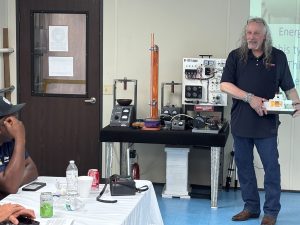
Another common cause of sea water entering the engine from the exhaust is over cranking the engine. If the engine fails to start and the engine is continued to be cranked, the sea water pump is pumping water into muffler. Eventually is will rise up the hose between the exhaust elbow and the muffler. That said, a perfectly designed exhaust system on an engine with good compression will evacuate the muffler before it enters the engine. We have proved this in our exhaust training classes with clear exhaust hose set up between the engine, muffler and out. But, is anyone interested in seeing if this is the case with your engine?
The solution is to open the cover on the sea water pump and remove the impeller until the engine starts. Once it starts, shut down the engine, replace the impeller and restart.
No discussion of the wet lift exhaust system would be complete without discussing the “gas/water separator”. In an effort to silence the splashing sound of most wet lift exhaust systems, a device was developed to separate the gas and water. The dry gas would exit vessel via the normal exhaust hose and the water would drain out below water line. This system is also helpful in some marginally designed exhaust systems. Space does not allow for a complete discussion of the gas/water separator but it, in itself, created new problems. The worst of these is carbon on the surface of the water surrounding the vessel. Often the carbon manifests itself a sheen or slick on the water. Another complaint can be “fuel on the water”. To determine if the cause is fuel or carbon, lay a white paper towel on the slick and then lift it up and inspect the paper towel. If it is carbon, you will see a black dot on the paper towel.
Another common problem with the gas/water separator installation is the assumption that the dry gas is completely dry. It isn’t. There is mist that escapes with the gas. If the dry gas hose does not run straight down and out like the wet lift system, but instead has bends up and down (what is referred to as water traps) the moisture will coalesce and fill those traps. The dry gas will have to build up enough pressure to push this out resulting in increased back pressure.
While discussing the subject of back pressure, we’d be remiss if we did not mention the effect of high back pressure on exhaust systems. All manufacturers set a maximum allowable back pressure. This is usually measured with a manometer in inches of water. The limits vary widely but they are typically 25 to 50 inches of water (one or two psi). High back pressure will shorten the life of an engine, at best, or can lead to the engine filling up with water and/or damage. Exhaust back pressure readings should always be taken on all new engine and generator installations.
This discussion has been limited to the conventional wet lift muffler. There are many other designs on the Market with their own advantages and disadvantages. Although the designs may vary, the principles remain the same. Back pressure needs to stay within limits. And the water trap needs to contain all the water in the system when the engine shuts down.
Wet lift exhaust systems will not work in every application. If the engine or generator is mounted low and in the middle of the vessel, a wet lift system may not work. What happens then? The ultimate solution may go back to the beginning and run an insulated or wet jacketed exhaust pipe out of the vessel. Or a dry pipe can be run to an area where a wet lift system will work. An example of this is Figure 7 in the “Don’t Drown Me” brochure.
Confused? Join the Club. But, if uncertain, find someone with a lot of experience in Marine Exhaust Systems and get their opinion. In the case of Marine Exhaust Systems, it may not be the person with the highest college degrees who is your best resource. Rather it is probably the guy who has pumped a lot of sea water out of engines (some of which may have been his or her own fault!).
DOWNLOAD OUR DON’T DROWN ME BROCHURE HERE


